Note. PIDs $24 to $2B shall be used for linear or wide-ratio Oxygen Sensors when equivalence ratio and voltage are displayed:
|
Equivalence Ratio (lambda) (Bx-Sy) |
A, B |
0 |
1.999 |
0.0000305 |
EQ_RATxy: x.xxx |
|
Oxygen Sensor Voltage (Bx-Sy) |
C, D |
0 V |
7.999 V |
0.000122 V |
O2Sxy: x.xxx V |
PIDs $34 to $3B shall be used for linear or wide-ratio Oxygen Sensors when equivalence ratio and current are displayed:
|
Equivalence Ratio (lambda) (Bx-Sy |
A, B |
0 |
1.999 |
0.0000305 |
EQ_RATxy: x.xxx |
|
Oxygen Sensor Current (Bx-Sy) |
C, D |
-128 mA |
127.996 mA |
0.00390625 mA |
O2Sxy: x.xxx mA |
Quotes from 2005 CAMRY SOLARA REPAIR MANUAL (RM1128U).
The Air-Fuel Ratio Sensor provides (photo) output voltage (the voltage value changes on the inside of the ECM only) approximately equal to the existing air-fuel ratio. The A/F sensor output voltage is used to provide feedback for the ECM to control the air-fuel ratio.With the A/F sensor output, the ECM can determine deviation from the stoichiometric air-fuel ratio and control proper injection time. If the A/F sensor is malfunctioning, the ECM is unable to accurately control air-fuel ratio.
Example: If the A/F sensor voltage output is less than 2.8 V (very RICH) for 10 seconds even though voltage output of the heated oxygen sensor output voltage is less than 0.85 V, the ECM sets DTC P2196 or DTC P2198.
If the heated oxygen sensor output voltage is 0.15 V or more but the A/F sensor voltage output is more than 3.8 V (very LEAN) for 10 seconds, DTC P2195 or DTC P2197 is set.
DATA LIST/ACTIVE TEST->:
Tester Display / Measurement Item-Range (Display) / Normal Condition / Diagnostic Note
PID "AFS B1 S1" / Minimum: 0 V, Maximum: 7.999 V / Idling 2.8 to 3.8 V / Performing INJ VOL or A/F CONTROL function of ACTIVE TEST enable the technician to check voltage output of each sensor.
ACTIVE TEST A/F CONTROL operation.
(5) Perform the A/F CONTROL operation with the engine idling. Result:
A/F sensor reacts in accordance with increase and decrease of injection volume:
+25 % " RICH output: Less than 3.0 V
-12.5 % " LEAN output: More than 3.35 V
Heated oxygen sensor reacts in accordance with increase and decrease of injection volume:
+25 % " RICH output: More than 0.55 V
-12.5 % " LEAN output: Less than 0.4 V
READ VALUE OF HAND-HELD TESTER OR OBD II SCAN TOOL (OUTPUT VOLTAGE OF A/F SENSOR)
Check the A/F sensor voltage output under the following conditions:
(1) Allow the engine to idle for 30 seconds.comm.gif (10876 bytes)
(2) Run the engine at approximately 2,500 rpm. Do not suddenly change the rpm.
(3) Raise the engine speed to 4,000 rpm and quickly release the accelerator pedal so that the throttle is fully closed.
Standard: Conditions (1) and (2). Voltage change of 3.3 V (0.66 V)* (between approximately 3.1 to 3.5 V) as shown in the Image.
Condition (3). A/F sensor voltage increases to 3.8 V (0.76 V)* or more when fuel is cut during engine deceleration as shown.
* Voltage when using the OBD II scan tool.
Diagnostic Toyota Solara a'05 with 3MZ-FE Engine: 4T1FA38P45U051510, 4T1CA38P75U059345, and Camry a 02 with 1MZ-FE Engine.
I checked its Vehicles by using AE PC-based Scan Tool with Enhanced Interface Toyota Expansion #EI03 (V4.3.) and I had the strange Results.
1. By V4.2 Toyota Enhanced Powertrain I see and don't understand (on these Cars) PID "B3S1 Wide Band O2 Sensor Voltage" (Solara , Camry). Its Vehicles not use Bank3. By betaV4.3.0 I had same Result.
2. By version 3.6. with Toyota Enhanced Powertrain I can look (measure) in Menu "Live Data Graphs" Signal "Current of Air/fuel Ratio Sensor" in "mA".
3. As we know (by iATN and Techinfo Toyota), normal data value for Wide Range Air/Fuel Ratio Sensor is as shown in this Image:
Note: This Solara is fault-free, not broken, well works: 13.980 mileage, no DTC, good drivability and fuel consumption (16mpg), and like as new.
The strange Data... Take a look Voltage on A/F Ratio sensor.
At Idle Voltage on AFS B1S1, that AE called B1S1 Wide BandO2 Sensor Voltage, show more then 7 Volt. But "B1S1 Wide Band O2 Sensor Equivalence Ratio is 1,000-O'k, SFTB1 and LFTB1 is good!
At Idle Voltage on AFS B1S1 show less then 0,5 Volt. By V4.3.0 I had same Result.
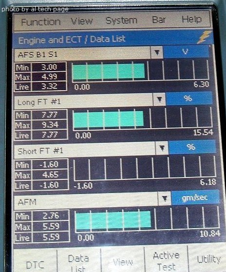
Other parameters (Data Value for other PIDs) are measured correct.
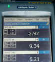
I check Live Data Graphs and had some results (liveData1 and liveData2).
By V4.3.0 I had same Result.
If I use Toyota Intelligent Tester II (photos), I can measure (look) correct Voltage of this Sensor of above Solara.
4. Completely not correct data in menu "O2 Sensors".
Note. Toyota has use new "Planar" A/F Sensor. A second generation it Sensor was developed to meet more stringent emission regulations. This A/F Sensor reaches operating temperature faster that the previous (aka Cup Element) A/F sensor. This allows the ECM to go into closed loop vuel control faster when the engine is cold reducing cold start emission.
Like previous O2 and AF Sensors, the planar AFS has ambient air on one side of the ZrO2 and exhaust gases on the other side.
The planar AFS has the same detecting range and signal characteristics as the previous cup element. But heater element has higher resistance! This AFS is not interchangeable with the older, cup element AFS. Heater Resistance (at 68 degr.F)=1.8-3.4 Ohm. The heater is imbedded into aluminum oxide. When the heater is ON, the aluminum oxide conducts heat directly to the zirconium dioxide layer bring the AFS to operating temperature quickly.
The heater monitor continuously detects over current or under current condition and set DTC in one trip. The never planar AFS can be identified by its shorted body (13 mm).