
Toyota Idle Air Control Valve
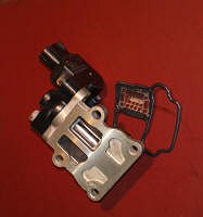
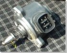
The rotary solenoid (RS) type IAC valve is located on the throttle body and intake air bypassing the throttle valve passes through it.
In this way the intake air volume bypassing the throttle valve is regulated, controlling the engine speed.
The ECM operates only the IAC valve to perform idle-up and provide feedback for the target idling speed. The IACV receives its power from the EFI relay and ground through the ECM. There are two styles of rotary solenoid IACVs. The older style uses two driver circuits, one driver for each coil. The newer style uses a single driver circuit, one coil is controlled by the ECM while the other coil is always grounded. They are not interchangeable. An easy way to tell which type of rotary solenoid is to use the wiring schematic. The older style has two wires connected to the ECM while the newer type has one connected to the ECM and the other wire connected to ground.
Rotary IACV Operation.
The valve assembly consists of two electrical coils, a permanent magnet mounted on the valve shaft, and a valve. A fail-safe bimetallic strip is fitted to the end of the shaft to operate the valve in the event of electrical failure in the IACV system. Located at the end of the valve shaft, the cylindrical permanent magnet rotates when its two poles are repelled by the magnetism exerted by coils T1 and T2. Anchored to the midsection of the valve shaft, the valve controls the amount of air passing through the bypass port. The valve, valve shaft, and permanent magnet all rotate together.
Strip As shown, each coil is connected to a transistor, T1 and T2 located in the ECM. When transistor T1 turns on, current flows through that coil. The magnetic field of the coil and the magnetic field of the permanent magnet cause the valve to rotate clockwise. When T2 is turned on, the valve rotates counterclockwise.
The ECM varies the on time (duty ratio) for each coil. The difference in strength between the two magnetic fields determines the position of the valve. The frequency is very high, 250Hz. This high frequency helps the valve maintain the correct position for proper airflow.
Single Driver Rotary IACV Operation.
The difference with this type of IACV is that the ECM sends a duty cycle signal to one coil inside the IACV; the other coil is always on. To change the IACV position, ECM changes the duty ratio in the controlled coil.
Bimetallic Spring Operation
If the electrical connector is disconnected or the valve fails electrically, the shaft will rotate to a position determined by the balancing of the permanent magnet with the iron core of the coils and the bi-metal strip. The cold idle will not be as fast as normal and the warm idle will be higher than normal. Using a bimetallic strip allows the IACV to change airflow rate with the change in temperature. The default rpm is approximately 1000 to 1200 RPM once the engine has reached normal operating temperature.
Rotary IACV Controlled Parameters
Engine Starting. As the engine is started, the ECM opens the IACV to a preprogrammed position based on coolant temperature and sensed rpm.
Warm-up. Once the engine has started, the ECM controls the fast idle based on coolant temperature.
As the engine approaches normal operating temperature, engine speed is gradually reduced. At this time the ECM is comparing actual idle rpm to the target rpm.
Feedback Control. The ECM utilizes a feedback idle air control strategy (which functions very much like the stepper motor IAC system). That is, when the actual engine speed is lower than the target idling speed, the ECM signals the IACV to open. Conversely, when the actual idle speed is higher than the target idle speed, the ECM signal the IACV to close.
Engine Load/Speed Change Estimate Control. To prevent major loads from changing engine speed significantly, the ECM monitors signals from the neutral start switch (NSW), the air conditioner switch (A/C), headlights or rear window defogger (ELS), and in models equipped with power steering, an oil pressure switch (PS). By monitoring these inputs, the ECM reestablishes target idle speeds accordingly, and adjusts IACV position.
Before a change in engine speed can occur, the ECM has moved the IACV to compensate for the change in engine load. This feature helps to maintain a stable idle speed under changing load conditions. These speed specifications can be useful when troubleshooting suspected operational problems in the IAC system or related input sensor circuits.
The Rotary Solenoid IAC system utilizes a learned idle air control strategy.
The ECM memorizes the relationship between engine rpm and duty cycle ratio and periodically updates its memory. Over time, engine wear and other variations tend to change these relationships. Because this system is capable of feedback control, it is also capable of memorizing changes in the relationship of duty ratio and engine rpm. The ECM periodically updates its memory to provide more rapid and accurate response to changes in engine rpm.
NOTE: If the battery is disconnected, the some ECM must relearn target step positions.
Feedback (Closed Loop) Idle Air Control
The ECM has a preprogrammed target idle speed that is maintained by the IACV based on feedback from the NE signal. Feedback idle air control occurs any time the throttle is closed and the engine is at normal operating temperature. The target idle speed is programmed in an ECM look up table and varies depending on inputs from the A/C and NSW signals. Any time actual speed varies by greater than 20 RPM from target idle speed, the ECM will adjust the IAC valve position to bring idle speed back on target. The ECM utilizes a feedback idle air control strategy. That is, when the actual engine speed is lower than the target idling speed, the ECM signals the IACV to open. Conversely, when the actual idle speed is higher than the target idle speed, the ECM signal the IACV to close.
PIDs (Data) by Scan Tools. Scan display: IAC DYTY RATIO;
Measurement Item: Intake Air Control Valve Duty Ratio (Opening ratio rotary solenoid type IAC valve, ISC DUTY CYCLE - Idle Speed Control -ISC- Valve percentage opening);
Normal Condition: Idling: 22.5-43 %.
Check Idle Air Control Valve (Step Motor Type)
INSPECT IAC VALVE OPERATION
Connect the positive (+) lead from the battery to terminal +B and negative (-) lead to terminal RSC and check that the valve is closed.
Connect the positive (+) lead from the battery to terminal +B and negative (-) lead to terminal RS0 and check that the valve is open.
If operation is not as specified, replace the IAC valve.
ON-VEHICLE INSPECTION
1) INSPECT IAC VALVE OPERATION(a) Initial conditions:
- Engine at normal operating temperature
- Idle speed checked correctly
- Transmission in neutral position
- A/C switch OFF
(c) After engine speed is kept at approx. 1,000 rpm for 5 seconds, check that it returns to idle speed*.
If the engine speed operation is not as specified, check the IAC valve, wiring and ECM.
(d) Remove the SST (or suitable jumper*) from the DLC1. SST 09843-18020
2) INSPECT IAC VALVE RESISTANCE
NOTICE: "Cold" and "Hot" in the following sentences express the temperature of the coils themselves. "Cold" is from -10°C (14°F) to 50°C (122°F) and "Hot" is from 50°C (122°F) to 100°C (212°F).
(a) Disconnect the IAC valve connector.
(b) Using an ohmmeter, measure the resistance between terminal +B and other terminals (RSC, RSO).
Resistance: Cold: 17.0 - 24.5 Ohm; Hot: 21.5 - 28.5 Ohm. If resistance is not as specified, replace the IAC valve.
(c) Reconnect the IAC valve connector.
Клапан ХХ подвержен загрязнениям. Пример очистки клапана (IACV clearing).
Сравните его состояние до и после очистки в этом видео мастер-класса и описании практического примера его ремонта.
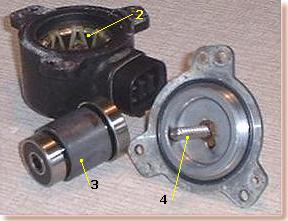
В более современных инжекторных системах используются Idle Air Control Valve, в которых с помощью шагового двигателя 2 вращается магнит 3. Посредством червячной передачи 4, перемещается шток 1 и изменяется сечение "обходного" воздушного канала. Т.о. изменяется количество воздуха, поступающего в цилиндры и, как следствие, обороты холостого хода. Данный узел позволяет отказаться от сложных регулировок, проще в обслуживании, надежней и, главное, позволяет точно поддерживать обороты ХХ. Для проверки клапана можно использовать (I make and use) ISCV Checker
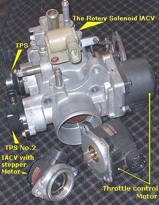
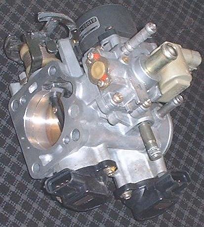
System with TRC use Electronic Throttle Control Systems.
Electronic Throttle Control System - intelligence (ETCS-i) has several advantages because the ECM will position the throttle valve for optimum performance. In a mechanical system, the opening rate of the throttle valve is controlled directly by the driver. ETCS-i can control the rate for better engine performance. On vehicles equipped with Vehicle Skid Control (VSC), ETCS-i will adjust the throttle valve to maintain traction on acceleration. The ISC system and cruise control functions are part of the ECTS-i system. There is also a limp home feature if the system is shut off.
The throttle motor operates the throttle valve. An electromagnetic clutch connects the throttle motor to the throttle valve. The throttle position sensor detects throttle valve angle. The accelerator pedal position sensor detects accelerator pedal position. The ECM adjusts the throttle valve angle in response to engine and vehicle conditions. Some versions used a thermostat to keep the throttle body at the proper temperature.
Operation The following describe the functions of the major components of ETCS-i.
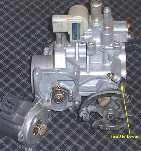
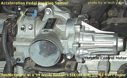
- Acceleration Pedal Position Sensor (APPS) - The APPS, which is mounted on the throttle body, is integrated with the throttle lever. The throttle lever is connected by cable to the accelerator pedal. As the driver moves the accelerator pedal the APPS signal voltage changes indicating pedal position. There are two voltage output signals from the APPS. The ECM uses these two signals to calculate the desired throttle valve angle. Also, by using two signals the ECM is able to compare and detect if there is anything wrong with the APPS's performance.
- Throttle Position Sensor - The TPS is used to detect the actual angle of the throttle valve. This signal indicates to the ECM throttle valve position and that the throttle valve moved to the desired angle. Throttle valve position detection is necessary for the ECM to make adjustments to the throttle valve position and to detect if there is a failure in the system.
- Throttle Control Motor - The throttle control motor is a DC motor controlled by the ECM. The ECM controls the direction and the amperage of the current through the motor. The circuit is pulsewidth modulated (duty ratio cycle regulated). If there is a malfunction in the system, the ECM shuts the circuit (and clutch circuit) off and the return springs close the throttle valve. The ECM will turn the motor off if there is excessive amperage or not enough amperage in the motor circuit.
- Magnetic Clutch - Under normal operation, the magnetic clutch connects the throttle control motor to the throttle valve. The circuit is pulsewidth modulated reducing power consumption. If there is a malfunction in ETCS-i, the ECM turns off the clutch circuit (and motor) if there is too much or not enough amperage in the circuit.
- Thermostat - A thermostat is installed in the throttle body to shut off the flow of coolant when coolant temperature is high. This prevents the throttle body from heating up the intake air reducing performance. The thermostat uses a wax expansion valve to open and close the coolant passage.
- Fail-Safe - If an abnormal condition occurs with the ETCS-i, the MIL will illuminate to alert the driver. At the same time, current to the throttle control motor and magnetic clutch are cut off. With no power to the motor or magnetic clutch, the return spring closes the throttle valve to the default position. In this situation, called limp mode, the accelerator pedal operates the limp mode lever. When in limp mode, the throttle can only be partially opened reducing engine power. Furthermore, ISC and cruise control systems will not operate.
ETCS-i Control Modes. The ECM drives the throttle control motor to a target throttle angle as determined by operating conditions. The following describes the different modes:
- Non-linear Control - Non-linear control means the ECM can control the throttle valve opening rate and position based on such factors as accelerator pedal effort and engine rpm to achieve better performance and comfort. In slippery conditions, the throttle valve can be controlled to aid in vehicle stability.
- Shift Shock Reduction Control - The throttle control is synchronized to the Electronically Controlled Transmission control during the shifting of the transmission to reduce the shift shock.
- Idle Speed Control - The ECM adjusts the throttle opening to maintain the target idle speed.
- TRAC Throttle Control - As part of the TRAC system, the throttle valve is closed by a demand signal from the ABS, TRAC, and VSC ECU if an excessive amount of slippage is occurring at the driven wheel.
- VSC Coordination Control - VSC performance is enhanced when the throttle valve opening angle is modified by the ABS, TRAC, and VSC ECUs.
- Cruise Control - ETCS-i eliminates the need for a separate cruise control system. Cruise control strategies and functions are incorporated into the ECM.
ETCS-i Throttle Motor Circuit Operation The ECM controls the direction and amount of current needed to activate the throttle control motor to adjust throttle valve position.
The throttle motor can be in any one of the following five modes:
- Default position
- Throttle closing
- Throttle opening
- Throttle hold
- Idle speed control.
The motor circuit consists of four control transistors on the MO and MC circuits. One transistor supplies power and the other transistor completes the path to ground. This configuration allows the ECM to control the direction of current through the motor. This circuit is also pulsewidth modulated to control the rate of throttle movement and to hold the throttle in a given position. For rapid throttle opening, the pulse width duty ratio will be high (current flow high) for rapid movement. To hold the throttle in the desired position, the ECM applies enough current to oppose spring pressure. If the traction control mode is engaged, the pulsewidth will be less, limiting the rate of opening from idle. If the throttle valve is opened too far, the ECM will decrease the pulsewidth closing the throttle.
Default Position When there is no current applied to the motor, the springs hold the throttle valve in the default position. This condition occurs when the engine ignition key is off or when the ECM has detected a failure in the ETCS-i system. When a failure is detected, current to the motor and clutch is turned off. These actions disengage the motor from the throttle shaft and prevent the motor moving the throttle valve. In this state, the idle is higher than normal when the engine is at operating temperature. The throttle valve will move if the driver presses down further on the accelerator pedal.
Throttle Hold To maintain the desired throttle valve angle, the applied duty ratio creates enough force in the motor to oppose spring pressure.
Idle Speed Control The throttle valve is adjusted to maintain the desired idle speed. If the desired idle speed needs the throttle valve below the default position, the throttle close circuit is activated. Any decrease in duty ratio will open the throttle valve and raise engine RPM. If the desired idle speed needs the throttle valve above the default position, the throttle open circuit is activated.
Diagnostics When ETCS-i is in Fail Safe mode, the driver will notice the pedal travel is longer in relation to engine response and that the MIL is on. Retrieve the DTCs and follow repair manual procedures.
Take a look for other info about ETCS-i System on old Toyota (Russian)Наиболее полноценно эту систему стОит диагностировать (анализировать состояние и возможные причины неисправности) by using PC-based Enhanced Interface Toyota Expansion #EI03 or Toyota/Lexus Intelligen Tester II or Toyota Techstream
УТТ Start Mode on Toyota (Russian)
Idle (Russian)
New Throttle Valve Control System